Polygon Smoothing Weirdness

I've been trying to better understand how the "Smooth angle" value works on polygon objects when either "Normal break" or "Constraint" is selected. To investigate this I created a "Ball" object with 8 longitudinal sections and 4 parallel sections and then flattened the top and bottom. There resulting shape looks like this:

1586379014902.png


This gives me a shape where all the sides have a common angle between the faces, but the top and bottom faces share a sharper angle with the sides. With a little math I determined that the angle between the vertex normals shared between one side face and another should be about 41.86 degrees and that the angle between a top face and a side face should be about 69 degrees.

Using this object, and starting with an angle setting of 30 degrees I watched the display as I stepping the value up one by one. I expected to see a transition where the side faces went from flat shaded to smooth and then, as the angle advanced higher to eventually see the entire shape display as smooth. Instead, I saw one transition stepping from 41 to 42 degrees, then another from 60 to 61 degrees and get another from 69 to 70 degrees. The shape displayed when angle is set to a value greater than 41 degrees and less than 61 degrees seemed to be some type of hybrid that is both smooth and creased. The shape from >= 61 degrees and <= 69 degrees was more like I expected with a flat top and bottom and completely smooth sides (relatively speaking.) And, also as expected, the shape when angle is >= 70 degrees was completely smoothed.

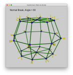
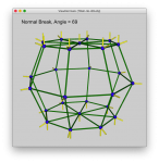
To investigate this further, I exported versions of the .jas file to a series of files in .obj format as I varied the smooth angle. I then used a view program I wrote in JavaFx to display the vertex normals exported for each file, as shown below:

1586380386784.png

1586380403340.png

1586380439673.png


1586380468257.png

As you can see, as the angle reaches a value of 42 degrees the vertex normals for the sides become only partially smoothed together and it isn't until the angle value reaches a value of 61 degrees that the side faces share a single, common vertex normal and display as fully smoothed. Perhaps there is something I don't understand about how C3D computes surface normals, but this semi-smoothed intermediate state doesn't seem quite right to me. Can someone explain? Is this a bug, or a feature I don't understand how to use?

Also, it would be nice to have a way to display vertex normals directly in C3D, as I think that would make it easier to understand what happens when the smooth angle is changed on other kinds of polygon meshes. My simple viewer can handle simple shapes, doesn't do so well on more complex ones.

Wayne
 

Attachments

  • 1586380418808.png
    1586380418808.png
    209.7 KB · Views: 219
  • 1586380453379.png
    1586380453379.png
    205.4 KB · Views: 213
From what I know Normal Break needs "Creases" to work. I'm not sure you've considered that or if it´s relevant.
PS: and there´ s a "Normal Checker.js" script created by Hiroto:
NormalChecker.png

Cheers
Frank
 
Last edited:
As Frank says use Normal Break if you use Creases.
I believe it makes it so the Smoothing setting doesn't override the Creases.
When a crease is used you don't want smoothing over it.
 
As I mentioned at the beginning of my post, I get exactly the same weird intermediate result if I use either "Normal break" or "Constraint".

1586468273802.png


1586468289660.png


1586468303488.png


1586468325498.png


It's a little hard to see, but there is a different between each of these screen shots. And, I get the same result as before if I export the same angle sequence to .obj files with "Constraint" selected and then bring them up in my normals viewer.

Wayne
 
I think I don´t get the point where you start to talk about "normal break".
I´m not sure what you´re after honestly. I either want it flat or smooth or both if necessary.
When you think there´s an error/issue maybe contact Martin. I´m not a developer.

Cheers
Frank
 
OK, I'm not a 3D developer and not even terribly well versed in 3D software, but I think you're both confusing which angles are involved in smoothing. The following are MY OWN SUSPICIONS, and I highly recommend a grain of salt with each and every one of them.

A) The angles used in these calculations have nothing to do with the polygon boundaries (I should have said points) - they seem to refer to the angles between the planes of the polygons at the point where boundaries occur.

B) The smooth angle seems to translate as "Smooth edges where the angle difference between these two planes is less than this value."

e.g.:

Set up the sphere with 8 longitudinal sections and 4 parallel sections, convert it to polygons and flatten the top and bottom.

Select one polygon on each side of the equator. Apply Tools > Polygon > Linear Subdivide. Delete the horizontal boundaries in the middle of each of those two planes.

What you have now is a pair of boundaries that represent the actual angle between the polygon planes ( 138.118° ), not the angle between the polygon's edges ( 135° ). Get the difference between the plane angles by subtracting that value from 180° ( 41.882° ).

EdgeAngle.jpgPlaneAngle.jpg

THIS is where smooth angles comes in.
Set smooth angle to 41.5°, and you'll see hard edges. Set it to 42°, and those edges will be smoothed.
41degree.jpg42degree.jpg
 
Last edited:
On closer examination, that may not be the exact math logic that's going on, but it's damn close. There's definitely a tipping point there.
41.jpg42.jpg
 
I think I don´t get the point where you start to talk about "normal break".
I´m not sure what you´re after honestly. I either want it flat or smooth or both if necessary.
When you think there´s an error/issue maybe contact Martin. I´m not a developer.

Cheers
Frank
First, thanks for trying to help answer my question. And, let me clarify what I'm asking about, which is to understand how Cheetah3D uses the smoothing angle value when generating vertex normals for polygon objects. My curiosity about this started when I noticed, in some more complex models I was designing, that using the smoothing angle sometimes produced results that didn't match my expectations. However, it was hard to debug in these more complex shapes. So, to investigate further, I created this simpler model as a way to better observe that happens as I changed the value of the smoothing angle in one degree steps.

With this model, I expected that there would be three ranges of angles where the shading on the model would change. Specifically, I expected to see one of the following as the angle changed:

1. A range of angles where all the faces are flat shaded with visible creases.
2. A range of angles where the top and bottom faces flat shaded and the sides are smooth shaded.
3. A range of angles where all the faces are smooth shaded.

Instead, I found there seemed to be four ranges of angles, as follows:

1. for angle <= 41 degrees, all faces are flat shaded with visible creases
2. for angle >= 42 and angle <= 60 degrees the top and bottom faces are flat shaded and the sides are "slightly" smooth shaded, but still visiblycreased.
3. for angle >= 61 and angle <= 69 degrees the top and bottom faces are flat shaded and the sides are smooth shaded.
4. angle >= 70 degrees all faces smooth shaded.

It is the curious #2 state that I'm trying to understand. Why does this state exist? Is it a bug, or am I misunderstanding something?

Wayne
 
Hi Wayne.
I´m not sure if I can shed any light into this "dark" area.
I´m somehow under the impression you either think there should be 1 smoothing angle which should be valid for the whole model of any complexity - or you still don´t get what "normal break- shading is meant for.
Somehow I lack the necessary tools to explain this to you:
(135° means 45° in this case - not sure why Cheetah3d adds 90° to it in the ruler tool. And "purple" edges are creased)
Normal Break.gif


Cheers
Frank
 
135 is the inside angle, the outside angle would be 225.
135 + 225 = 360
Cheetahs ruler tool only goes to 180, being a straight line or flat.
 
I'm trying my best, I believe I have a clear understanding.
If the ruler measures 180 between in line polys, the smoothing considers it to be zero.

Change the poly angle to 135. That's 360 - 135 = 45
So now 45 degrees is the angle difference between faces.

Invalid test

If it's an outside corner a Smoothing setting of 1 to 45 will be a hard edge.
If it's an inside corner 1 to 44 will be a hard edge for some reason.

This shows the difference between inside and outside corner
behavior which must be determined by the direction of the normals.

Changing between a smoothing value of 45 and 44 degrees.
The 45 degree inside corner is smooth at a Smooth setting of 45 but not 44 or less.


smooth_one.gif
 
Last edited:
I just tried flipping the normals to see if anything changes, but it does not.
So I don't know what's going on there, I need more pointless testing. :oops:
 
One of my 45 degree angles was off by a tiny bit, not enough to show on the ruler, but enough to to change smoothing.
No difference between "inside" and "outside" corners as far as smoothing behavior.

All other info checks out.
 
OK, to sum up*, here's my take on what is going on.

SmoothExplanation.jpg

This is an edge-on view of the intersection of two polygons, with the black line being those polygons. Because we are looking at a cross-section, it's in 2D.

The blue line represents a smoothed boundary edge between the two polygons,
The dashed gray line is an imaginary extension of one of those two polygon planes, and
The green lines are the normals to those planes (tangential to each polygon).
We are looking straight down the length of the intersection between those two planes, which, to Cheetah3D, is a boundary edge.

The Ruler displays the interior angle of those polygons. The smooth angle value looks at the angle between the imaginary plane extension and the other plane (the Difference Angle = 180° - Ruler Angle) OR it's looking at the angle between the normals to those planes, because those two values will ALWAYS BE THE SAME (Normal Angle = 360° - Ruler Angle - 90° - 90°).

If you provide a smooth angle value, you are - in effect - asking C3D to smooth any Difference/Normal Angle smaller or equal to the value you provide.

By experimentation, I'm seeing that the only real difference between "Constraint" and "Normal Break" is (as ZooHead suggested) that Normal Break respects Creases, Contraint doesn't.

The Smooth angle value is meant to represent the test value for the angle between the normals or each polygon.
Constraint: Anything less or equal gets smoothed, anything more is left as a hard edge.
Normal Break: Anything less or equal gets smoothed unless it is designated as a Crease, anything equal or more is left as a hard edge.

(for non integers, remember that computers don't always show you all the digits, and computer chips don't always do math perfectly)

The model used is the same as I described above, except for the addition of Creases around one of those planes.

Constraint 41.5°Contsraint41.jpg
Constraint 42.5°Constraint42.jpg
Normal Break 41.5°Normal41.jpg
Normal Break 42.5°Normal42.jpg

*all info is from what I've read, and what I've seen.
( I've edited some mistakes via italics and strikethroughs )
 
Last edited:
By experimentation, I'm seeing that the only real difference between "Constraint" and "Normal Break" is (as ZooHead suggested) that Normal Break respects Creases, Contraint doesn't.
Actually it's meant the other way around: Normal break needs creases to work. Say you have a complex model with all kind of smooth angles you are in the need to use Normal break shading to maintain different angles, where at every crease the shading will be new calculated.

Cheers
Frank
 
Back
Top