Spline Animation into Morph Tag?

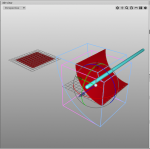
Anybody know a way to do something like this, but save the animation in a tag or some other way? A long time ago I animated this spline to show a clear piece of acrylic bending / flexing in and out of a sign and also a piece of paper. It would be helpful if I could re-use this animation more easily.

Frank helped me way back with figuring out how to save a point animation for a standard mesh (sucker tool) into a morph tag. I'd like to do something similar with the spline shape. Any suggestions are welcome Thanks!
 

Attachments

  • Flex & Sucker.jas.zip
    95 KB · Views: 214
I believe you can record the spline points via point aimation as well (not @iMac right now).

Cheers
Frank

Thanks Frank,

That's how I did these, but I was hoping there was a way to save that animation into some type of slider or pose control. For now I have to manually copy the mesh into another file and then copy and paste the keyframes after that. I know that the Morph Tag doesn't work on splines, but maybe there is a script somewhere that can do something similar?

The suction tool is pretty easy now to use in any file as it is, because the morph sliders make it really easy to modify the animation to whatever particular scened it's needed in. You showed me how to do that a few years ago, and it's been a big help and time saver.

Edit:
I suppose there may be a way to do this with bones and the Spline IK tag? I've never used that tag before.
 
* I may misunderstand your aim, but:
* Is not a simple bend modifier (x 2) / a cylindrical wrap applied to the acrylic (perspex / plexiglass) sheet sufficient?
* This is just a parametric "square" plus associated hierarchy which you can copy and paste to a variety of display units.
* You can easily adjust the parameters of the panels / the curvature of the bends / wraps as required. It seems that copy & paste takes along the associated parameters, so you just need to fine tune the settings.


Screenshot 2019-09-17 at 19.54.44.png
 
Thanks Helmut,

The problem with the Bend and Wrap modifiers are that they do not do asymmetry very well. There is also a problem with distortion, which these real parts can flex, but they should never stretch. The surface area should always be maintained. With a spline, I'm at least able to measure the length with each bend step in Illustrator to make sure that the width never goes past the width I need. But this is one of the reasons I'm looking for some other solution, as it takes a lot of prep work to get the spline/point animation correct. Depending on the sign holder that I'm animating, they have different types of inserts that are removed different ways. Inserting a panel is typically pushed from one side into the railing lip and then the part is flexed like a bow to push the other side into the railing (if that makes sense?). Removal of the insert is more symmetrical, but not perfectly. Most people when pulling the insert out, will pull one side out of the railing and then the insert is free to be removed the rest of the way with no more tension on the part. (The amount of tension depends on the insert material, thickness, and overall size.)

Also, nice suction pig! Here's mine from a few years ago. :p
 

Attachments

  • Suction Pig.png
    Suction Pig.png
    354.1 KB · Views: 190
* Yep, Frank´s solution is a bit simpler than having 2 bends. I just was assuming that you wanted to show some sort of "flutter" of the vertical edges as the two panels separate.
Sorry, edit conflict.
 
* Yep, Frank´s solution is a bit simpler than having 2 bends. I just was assuming that you wanted to show some sort of "flutter" of the vertical edges as the two panels separate.
Sorry, edit conflict.

I do like have some of the flutter on the edges. It makes it look a little more realistic. Frank's solution can work for insert removal. Especially for smaller inserts that use 040 clear PETG.

Thanks to both of you for taking the time to help.
 
Here's a file with the lens being inserted, if that helps any.
 

Attachments

  • Flex & Push.jas.zip
    16.7 KB · Views: 217
The plane is still in parametric shape and can either get records on the width or add a transform-modifer to adjust the width when it bows.

Cheers
Frank
 
* I spent some time checking the bend modifiers which I have suggested above:
1 just visually / by eyeballing with image & isolines on a smallish grid
2 formulaic, ie Arc Lenght = central angle of circular sector / 360° * 2r π) and central angle° = AL / r
3 using the C3D ruler tool to verify distances & angles of subsections

* I have deployed a fairly large JPEG of Breughel´s Tower of Babel and some regular geometric patterns (checker boards and stuff) to check image based artefacts.

:unsure: I can detect no visible distortion (iMac 27, zoomed to almost pixel distance to the Breughel). Algebraically, there can be a minor inconsistency (3rd decimal digit). This may be due to distortion or it could be a rounding error.

Screenshot 2019-09-18 at 10.11.36.png
 
@Helmut ; I´m fairly lost in your explanation and application. If I recall correctly the main issue with bending/morphing/etc a sheet is it has to get smaller in the width when pulled/bowed - which can be addressed by scaling of course:
Bent.jpg


Cheers
Frank
 
* It depends on the modifier and the specific geometry.

Screenshot 2019-09-18 at 11.50.21.png

1 Bulge / Pinch / Taper
* Original square shown in wireframe
* the modified square is distorted (a > 1 if bulge +ve, a < 1 if -ve)


2 Bend
* Original square shown in wireframe
* the modified “square” is not distorted
* Of course, the square is no longer flat, it is a 90° cylinder, the axis being shown as a blue capsule
* If I calculate the length of the arc (where the angle subtended is 90° to keep it simple) I get very close to 1.0 using the above formula. The minor imprecision stems from me just estimating the radius of the bend and its misfit with the 15 digit precision of π.

* Of course, this only holds for the most simple and trivial of configurations. In the moment you introduce any rotation matters get a bit tricky.
 

Attachments

  • Screenshot 2019-09-18 at 11.50.36.png
    Screenshot 2019-09-18 at 11.50.36.png
    114.9 KB · Views: 205
Thanks for the input Helmut and Frank!

I didn't even think of trying to use soft selection with a morph tag. I'll delve deeper into these methods.
 
This show's how I originally set up the bend. I had to make sure the length always stayed the same in Illustrator using CADtools.

Bendy.png
 
* Thank you for providing the details of the topdown / X-section plan of the frame.
* I plan to investigate the “morphing” from flat plane to flexed (and vice versa) using my original concept of bend modifiers tomorrow CET.

* It may be :oops: (or may not be :mad:) possible to produce an animation which:
1 does not produce distortions
2 can be copied / pasted to related frames of different dimensions with minimal effort

* I expect that it is possible, :unsure: but there may be unknown limits to my infallibility

Tomorrow is another day.
Servus to Scarlett O´Hara from Vienna
 
Back
Top